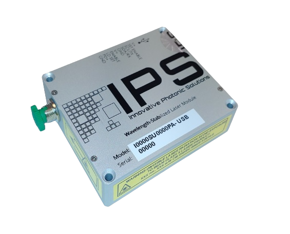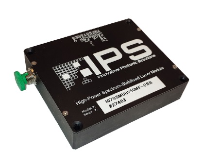
Our proprietary multi-spatial-mode wavelength stabilized Multi-Mode Digital U-Type Module features high output power with ultra-narrow spectral bandwidth.
Raman Spectroscopy
|
Portable Raman Equipment
|
Process Raman |
Fiber Laser Seeding and Pumping
|
Difference Frequency Generation and Gas Sensing
|
Remote Sensing
|

Pin |
Pin Label |
Function |
|---|---|---|
| 1* | V+ | Power Supply: 5V-12V. For lasers operating <600mW, a 5V minimum is required. For lasers operating >600mW, a minimum of 9V is required, 12V recommended |
| 2^ | VBIAS ENABLE (Set Enable) | For analog control: Enable external laser pwoer control through pin 8 (LD VBIAS): High (>3.6V up to V+ supply voltage) = Enable Low (GND) = Disable The same Functionality is emulated via software as a replacement for this analog control. |
|
|
SCL/TX | I2C: SCL standard (RS232: TX; board by request) |
|
|
|
I2C: SDA standard (RS232: RX; board by request) |
| 5** | GND | Ground |
| 6* | V+ | See Pin 1 |
| 7 | Enable | Laser Enable:
TTL High (>3.6V up to V+ supply voltage) = Enable |
| 8^ | LD VBIAS
(LD Set) |
Laser power setpoint – Enables analog external control of laser drive current. Drive VBIAS Enable (pin2) high to enable this option. Drive voltage between 0V and 1V. The voltage bias will be a 1:1 ratio to the laser drive current. See Operational Note #6. |
| 9^ | PD+ | For analog readout. Connect voltmeter to PD+ (pin 9) and GND for photo diode V output (0V-3.3V). The same functionality is emulated via software as a replacement for this analog control. |
|
|
|
Ground |
Pins 1, 2, 6, 7 and 10 are required for laser operation
Notes:
*Power must be supplied to both V+ pins (pin 1 and pin 6)
**GND must be supplied to both GND pins (pin 5 and pin 10).
^ Pins 2, 8, and 9 are optional for analog control/readout